Close
Search
Filters
RSS

Blog

Aluminium Profiles - What are They?

Aluminum extrusion and profiles

in this post we will cover:

What are aluminium profiles and extrusions?

Why use aluminium profiles?

How to use aluminium profiles?


What are aluminium profiles and extrusions?

Ok so first, what is an aluminium profile, extrusion? By the term aluminium profile, people refer to an extruded aluminium profile that has structural integrity and attachment points formed from its profile. Another term that is used is T-slotted framing. Examples of profiles are shown below:

There are a lot of different types of extrusions i.e. cross-sections of aluminium profiles. The most common one is a square type with T-slots on all four sides. There are also different sizes, shapes, coatings, even curved profiles..


Why use aluminium profiles?

If you need to make a structure that requires substantial structural integrity, is not under high vibrating loads or forces and does not have to be super-precise then aluminium extrusions are the way to go. (Here we are talking about precision under 0,1mm (0.03″) ). Most common uses are for enclosures, guards, working stations, machine structures… There are also a lot of industrial machines that have their entire frame built out of these profiles. In automation and mechatronics they are also pretty common.

If you need to make a structurally sane enclosure you have a possibility to make it out of steel. You would then have to weld the stock bars, then grind them. There is a possibility that the structure will bend after welding so you might possibly have to machine it. Then for every attachment on the structure holes have to be drilled, so machining again. And then protect the material, usually by painting it. This is very laborious process. It definitely has its place and building with these profiles has limitstions. Because of that for some less challenging applications the aluminum extrusion structure is the way to go.


How to use aluminum profiles?

Aluminium extrusions are meant to be cut to size and attached one to the other by using fittings that are designed for this purpose. When you want to make a structure you need to figure out how to build it from straight parts of aluminum extrusions. For example a box like shown in the sketch bellow will be transformed so that every edge of the box is one aluminium extrusion.

Something like this example shown bellow. In this example the box is made out of 40×40 aluminium profiles. That means that profiles have dimensions of the cross section 40mm by 40mm.

Transforming straight lines from the sketch into aluminum extrusions is pretty basic. The only thing to consider is the size and shape of the profile. For carrying loads and similar information consult your supplier’s information. Connecting the profiles together is one thing to pay attention to. As mentioned above, the profiles have T-slot grooves along their length. There are a few different types of special T-nuts that are used for these slots.

 
Aluminum profile fasteners - what types exist and how to use them

In order to make a structure out of aluminium extrusions you need a way to fasten them. The first step that is covered in this post covers the use of aluminium profiles or extrusions, here we will cover aluminium profile fasteners.


Types of aluminium profile fasteners

There are many types of fastening aluminium extrusions, here we will focus on right angle fastening. I have used these profiles extensively and I have never had a need to connect profiles at an angle. So the right angle connection is enough to cover most of your needs. Here we are talking about connection two aluminium profiles. For connecting other stuff to aluminium profiles the most useful connection is a T-nut or a T-bolt. T-nuts were mentioned in the previous post.

There are a lot of different types of fasteners for aluminium profiles. Some manufacturers even have their proprietary type(s). I will cover the ones that I have used so far and these are also most common ones. If you come by some other types I believe that they will be similar to some mentioned here.

First the obvious ones.


Aluminium profile fasteners – 90 degree flat plate

Probably the easiest way to connect two profiles together. It’s pretty simple. All that you need are T-nuts some screws, DIN 7380 or others, and a plate with holes. You can make the flat plate by yourself pretty easily. For angled connections flat plates can also be used.


Aluminium profile fasteners – Gussets

Gussets are a simple strong method of connecting aluminium plates. For a gusset connection you will need T-nuts with screws for each screw hole on the gusset. Using gussets in the aluminium extrusion frame is similar to using gussets in a welded frame. Advantage over using the flat plate is that using gussets gives you clean sides of the frame. These connections are for right angle connection only.

Image Credit: http://www13.boschrexroth-us.com/Framing_Shop/Product/Default.aspx?category=10201

The names of the next couple of fasteners are borrowed from the resource’s dictionary. There might be different names from different manufacturers.


Aluminium profile fasteners – Automatic set

Automatic fasteners are advertised as “The fastest and most flexible profile connection”. The truth is that they are not very useful in my opinion. In the rest of this article you can see how to use them. For a secure connection you will need two of these fasteners. That just adds time in the assembly process. Also I personally do not see any benefit on using them over the other types.


Aluminium profile fasteners – Universal set

Universal set is one of the most commonly used. I believe that they are the highest strength connections. They are flexible connections because position of the profile beams can be adjusted even after the connection is set. Not all connections are like this. Standard set that we will talk abut later are clearly a rigid type. This fastener has always been the default one that I have used.


Aluminium profile fasteners – Standard fastening set

Standard fastening set is also a common one. A bolt and a proprietary washer make up this simple connection. This washer its into the groove of one of the extrusions. The other extrusion has thread cut into its center. The bolt secures the two profiles like in the picture bellow. This connection is rigid as that in order to tighten the bolt you need to provide a hole for a screwdriver or a hex key. These connections are commonly used as they are cheep and commonly available.


Aluminium profile fasteners – how to install


Automatic fastener -how to install

Process of installing automatic fastening set is presented in this video. Here the threaded part of the fastener is driven into the profile in order to cut the thread. This method is OK to use if you do not have a lot of connections. It does get tiresome after 10 or more connections.


Universal fastener -how to install

Here a video demonstrates how to use universal fasteners. In this video the holes are drilled “by hand”. It is not that easy to just drill a hole by a hand drill. First the position of the hole needs to be in +-0.5 mm so you do need to measure before you start drilling also the hole needs to be pretty large ~20mm so you need to hold the aluminium profile in a vise in order not to move. The easiest way if you have a lot of profiles to connect is just to mill the hole for the fasteners.


Standard fastener -how to install

In this connection you can see that a thread needs to be tapped in one profile and then the fastener is inserted. The second profile needs to have a hole drilled in order to tighten the bolt in the fastener. The video shows these holes drilled in the assembly process. When the right placement is selected you drill a hole for a hex key. The more realistic approach is to design the placement of the hole and to pre-drill it. This connection is rigid in the sense that is you want to move the connection slightly you would need to drill another hole for the hex key.

I hope that this post was informative. Now you have some basic knowledge on how to connect aluminium profiles.

Pneumatic Solenoid Valve Manufacturer and Supplier within the USA

For a wide range of valve related products, make sure to check out anixusa's product pages above!

ANIX VALVE USA

What are pneumatic solenoid valves?

Pneumatic solenoid or control valves are the “Lego blocks” of pneumatic control system. They are bought as functional blocks and integrated into the system. Every type of control valve has a symbol. Something like 5/2, 5/3, 3/2 and similar and they always have a schematic. Usually on them like you can see on the picture bellow. If these schematics look confusing do not worry there are rules on how to read them and they are pretty simple.

So the first thing is to cover the components of the schematics:


Pneumatic solenoid components

Here is an example of the schematics of a simple solenoid valve. This is a so called 3/2 control valve.

Schematic of a 3-2 control valve

On this schematics you can recognize different symbols:


  1. Square– denotes a state of pneumatic control valve i.e. its position. Usually there are two and three states of a pneumatic control valve.
  2. Actuator– denotes what force is changing the states (squares) or what actuates the valve: a solenoid (top one), a button, a spring (bottom one)….
  3. Arrows– show the direction of the air in the square. For example the air flows from port 2 to port 3 in the schematics above
  4. T – denotes that the port is closed. The air can not get into the control valve or escape it.
  5. Numbers (1,2,3,4,5) – denote the physical connections on the control valve. The connections are ports to which you can attach pneumatic hoses.

Reading a pneumatic solenoid valve scheme

3/2 control valve

Schematic of a 3-2 control valve

Here we have 3 ports. These ports represent physical ports on the control valve body so they do not change. First we look at the right state. We can see that in this state air flows from port 2 to port 3 and the port 1 is closed with a T-symbol. We can see that by noticing what numbers are connected via arrows.

OK now let’s look at the left state of the same control valve. Imagine that the left state shifts over to the right. If we now look at the numbers lining up to the new state we can see that air flows from port 1 to port 2 and the port 3 is closed with a T.

So now you know what states a control valve has and how do these states direct air flow. But how are these states actuated? Here is where we look at the actuator symbols. On the left side we see a symbol for a solenoid and on the right side we see a symbol for a spring actuator. This means that the left state is actuated with a left actuator – solenoid and the right state is actuated with a spring. In different words in order to “engage” the left state of the valve you need to actuate the solenoid. This also means that the right state is the default one. Since if there is no power the spring will actuate the right state. This is a convention. The default state is always shown on the left side by this convention.


5/3 control valve

What about three state valves like:

5/3 control valve

Here the middle state is the default one and left and the right state are actuated with solenoids. Springs are actuating this default state. This is also a convention, that in a 3 state valve the middle one is the default one.

So if we analyze the 5/3 control valve schematic that explain it as:

The control valve has three states and 5 ports. Air does not flow inside a control valve in the default state the (All ports are blocked with a symbol T) If we actuate a solenoid valve on the left side we actuate the second state and now air flows from 1 to 4 and from 2 to 3, the port 5 is blocked. If we instead actuate the right solenoid then ports 4 to 5 are connected and ports 1 to 2 are connected. In this state port 3 is closed.

What about the numbers like 5/3? This just represent the number of ports, 5 in this case, and a number of states- 3 states in this case. That is why in the first example the symbol was 3/2 – 3 ports and 2 states.

Machining large workpieces in one setup - Things to consider

Designing machines you have, or certainly will, encounter that you need to machine a large stock of material on the mill. Large workpiece is typical for machine structure. Any large piece of stock for you will want to machine in the minimal number of setups. Ideally in just one setup but this is more often than not not possible. Machining large workpieces can be made very expensive by poor design. Here are some things to consider whend designing with large parts.

There are some things to consider when designing a large pieces of the machine so that it can be easily setup and machined

First thing, and the most obvious is to check the maximum workpiece size that machine that you plan to use has. This is a spec that is easily found for every machine. For example the maximal travel of the axes for this HAAS VF-4 is 1270 x 508 x 635 mm. But these are not the maximal dimensions of the workpiece, they are smaller.


Clamping the workpiece

First you have to take into the consideration that the piece has to be clamped to the table. Most usual clamping system is with clamps such as the ones shown here:

The table is usually larger than the axis travel so this is not a problem and If the workpiece has holes cut out that are distributed well enough that the hold-downs can be set up so that they do not eat into the space of the machine travel. There are workarounds but this is something to take into the consideration.


Large workpiece -Tool path

Second thing and the one not so obvious is that these numbers are the maximal travel of the axes and not the maximal parameter the tool can make. You see, every tool has a diameter and therefore in order to machine a side the tool needs to be offset from the workpiece and this eats up into the space. The photo below illustrates this compensation when working with the G-Code.

The compensation for the tool needs to be factored in. When machining a large workpiece, or lets say a plate, it is usually of a larger thickness, so more rigid end mills need to be used. Let’s say that the plate is ~50mm thick. To easily machine the sides with a good surface finish you would need an end mill of at least 20mm diameter. Also this tool needs to lead into the part too. Depending on the setup and the machine this also needs to be factored in. All of this means that the maximal workpiece is shorter per axis at least for the diameter of the tool.


Recap

So when designing you need to consider following things:


  1. The maximal travel of the axes on the machine that will be used for machining.
  2. How will the workpiece be held-down. Does this eat into the workpiece size
  3. Considering the thickness of the plate, what is a minimal endmill diameter that can easily be used and what is the tools ramp in. For the maximal workpiece dimension that is close to the maximal machine travel subtract the diameter of the endmill (2x radius for both sides)

Last thing what if the part needs to be bigger than the machine’s workable size?

Then you can combine a few more manageable plates and connect them together. There are many ways to connect the plates (workpieces) but this is something that will be mentioned in the future blog posts.

Hope that this was usefull for you,

How to Transport and Secure Valves Safely and Efficiently

Check out Anix's line of valves in the product pages above!

Picture of ANIX Stainless Steel 2-Piece FIRE SAFE Full Port Ball Valve 2000 / 3000 WOG Threaded NPT

Valves journey from the manufacturing facility to the buyer is often an overlooked issue. The worst thing is that this problem more often than not becomes obvious at the last moment when the valve needs to be shipped. Then there are always some last minute solutions and hacking to load it on to a truck and ship it. The results are non-adequate solutions that can compromise the safety and risk damage. Transporting your creation to the desired place is also a part of valve design.

There are two problems to solve here:

1. How to move the valve around the facility and load it onto a truck / crate / shipping container and

2. How to secure the valve in the truck / crate / shipping container.

Let’s start with the first problem, transporting the valve around the facility.

Depending on the size and weight I can think of three possible solutions:


Small valves – make a wooden crate

Wooden crates are often used because the wood is readily available and easy to process. Also it’s softer then all metals so it cannot damage the goods. Crates obviously need to be large enough to contain the valve but also need to one additional feature. On the bottom of the crate wooden risers need to be added so that the crate can be easily lifted with a fork lift. These risers also help when lifting the valve by hand. The height of the risers is determined by the height of the forks on the forklift. Check out the download section bellow for the resource on how to design the crates.

Wooden crate design


Medium valve size – provide Lifting Eye bolts

Lifting Eye Bolt

Eye bolts are designed to be anchor points for securing the object. Eye bolts provide a thread on one side and a loop for fastening on the other. This method for securing has the benefits as the eye bolt can be removed after transporting. Through the loop, you can insert tying straps or you can insert a rod through two eye loops to help with the lifting with a lift. Again look at the download for additional resources and carrying loads.


Large valves – provide a spot to insert the forklifts forks

The first thing that you need to consider is the size of the valve and the weight of the valve. Weight of the valve is important because you will need a forklift with a larger lifting capasity in order to lift the valve. Forklifts with larger lifting capacity have larger forks so you need to put that into the consideration. I have tried to find out what are some of the standard sizes for forks regarding the lifting capacity but I was not able to find any. The best place to look for these information will be the forklift’s spec sheets.


The size of the valve is important because the center of mass of the valve needs to be located in the middle of the forks. If the valve is too big, so that the forks cannot reach the center of the mass the lift will not be possible. One way around this is to mount fork extensions on the forks. When designing a spot for the forks you need to consider the maximum width that the forks can expand and as mentioned the size of the forks themselves. The easiest thing to do is to sketch out these dimensions like this:

Forks sketch

Then design the openings for the forks to be bigger at least 20mm (~1″) in both dimensions. The width of forks opening with should be smaller than the forklift’s maximum, but try to keep it as wide as possible for stability.

A good idea is to provide a U beam for the forks. The beam will guide the forks inside the valve. Also weld a plate on the end of the beam so that the forks have a stop.

If the valve is high enough you can provide 2 L brackets just to keep the direction for the forks.

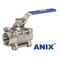
 Picture of ANIX Stainless Steel 3-Piece Full Port Ball Valve 1000 / 2000 WOG  Threaded NPT

Forklift spots recap:

  1. Determent the size of the forklift that you would need to move the valve
  2. Determent the size of the forks with or without extensions and the width that the forks can expand to
  3. Find the U beam that has internal profile dimensions at least 10-20mm larger than the forks.
  4. Mount the two U beams inside the valve as low and as wide as possible

In the part 2 of this mini series we will discuss the basics of tying the load in the shipping vehicle of transportation. You do not want to see something like this happen to you

American Coupling Manufacturer Based in the USA and Texas

Check out Anix's line of couplings by visiting the Product pages above!

Shaft couplings are mechanical components that are used to connect two rotating shafts. These components come in a lot of variation but all have the same basic functionality. Shaft couplings are used to transmit power and torque from one shaft to another. They also provide a disconnection point between the shafts for maintenance and repair. Shaft couplings also allow for misalignment between shafts. The simplest one that do not allow misalignment are similar to the shaft collars. The only difference is that they connect two shafts to transmit power. Like sleeve or muff coupling.

ANIX VALVE USA

Why use shaft couplings?

Using shaft couplings has many benefits such as:

-providing a disconnection point

-tolerating misalignment in the shafts (parallel, angular and axial)

-reducing the shock loads between shafts

-altering the vibrational characteristics of rotating units

-protection against overloads and others…


Possible misalignment when connecting two shafts

Angular misalignment in shafts is produced when axis of two connected shafts intersect at an angle. Proper coupling selection can easily mend this is a typical misalignment. Misalignment up to 5° or even more can be fixed.

Angular misalignment

Parallel misalignment is produced when axis of shafts are parallel but are no intersecting. They are offset by a certain amount.

Parallel misalignment

Axial misalignment is more rear but it can occur. This is the effect where the distance between the ends of the shafts changes during operation.

Axial misalignment

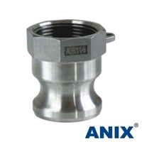
Picture of ANIX Stainless Steel 316 Camlock  Adapter Type A

Choosing shaft couplings

When choosing the shaft couplings for your project you need to take the following things into consideration:


  1. Do shafts have misalignment? If there is any misalignment, parallel, angular or axial the rigid muff shaft couplings are not the best choice
  2. Is the application motion control or power transmission?
  3. Motion control application are such applications where the motion of the output shaft is controlled or the position of the shaft is measured. Like in a servomotor or encoder. In these application there must not be any backlash in the movement. This backlash will cause false readings and therefore in not usable. There are shaft couplings that have zero backlash and those are a good option for this application.
  4. Power transmission application are applications where the main purpose is to transmit the power from on shaft to another. One shaft is usually connected to the power source. Most common applications are pumps, compressors, generators… In this cases the backlash in not important. The most important factor is the efficiency of power transmission.
  5. Required torque. The rule of thumb is that couplings with elastic elements can transmit less toque then couplings with all rigid elements like chain or gear connection. Whatever the case the torque rating is provided for every shaft collar by the manufacturer. Remember it is best not to choose the coupling with the maximum torque equal to the operating torque of the motor. Always choose a coupling with enough safety factor in order to be sure that the peak torque will not prematurely damage the coupling.
  6. Constant velocity. Constant velocity can be important in some application. Rigid couplings provide a constant velocity but if you need to manage misalignment then you can not use them. Elastic couplings do not provide a constant velocity because of the deformation of elastic elements inside them. The solution are special couplings that can deal with misalignment and also provide the constant velocity. Most common examples of these are universal joint, Thompson coupling and others.

Most typical shaft couplings in use

Jaw shaft couplings

Jaw shaft couplings are a typical coupling that has found useful applications in many areas. The coupling consists of two metal crowns that connect to both shafts and a spider that is made from elastomer. This elastomer spider is the connection between two crowns. The elastomer comes in several hardness options. The harder the elastomer spider the more torque the coupling can transmit but the dampening is lowered. In general engineering elastomer hardness of 92 Shore-A is a good compromise. Most of these couplings are backlash free so these couplings are suitable for use with servo motors. They are a bit to cumbersome to be used with encoders.


Beam shaft couplings

Beam shaft couplings are made from one piece of metal that is cut in the certain helical pattern. This is a type of flexture that connects the two shafts to transmit power. Because of their construction these type of shaft couplings do not have any backlash. They can handle a lot of angular misalignment up to 7°, and also slight axial misalignment. They cannot transmit the same amount of torque like jaw, or some other couplings. Beam couplings usually connect encoders and low powered motors.


Gear shaft couplings

Gear couplings are made out of two flanges with external gear and one sleeve with internal gear that goes over the flanges. The sleeve can be made from one or two parts that are connected together. Two component sleeves have stops on either side to stop the sleeve from disengaging with flanges. They usually transmit more power and torque. One component sleeve slides over the geared flanges and if not careful can disengage spontaneously. Lower speeds are necessary when using these couplings. Metal or plastic are the material of choice for these components. Plastic coupling improve dampening but reduce the power transmission capability.


Chain shaft couplings

Chain shaft couplings are usually used for power transmission applications. They can transmit a lot of torque, significantly more than couplings with elastic elements. The chain provides easy and fast decoupling. The couplings can have standard chains like the DIN8187 or proprietary like shown in the coupling in the picture bellow. Chain couplings can handle some angular misalingment, but not parallel or axial.


Other couplings

There are some interesting couplings to check out that have not made it into the list. Best examples of these are Oldham and Schmith shaft couplings. Parallel misalignment is allowed with these couplings. These couplings are in use in particular industries and are not seen every day, but when you have a particular problem to solve they can help you.

American Butterfly Valve Manufacturer and Supplier

Check out Anix's wide range of Butterfly valves in the product pages above!

ANIX VALVE USA

The term Butterfly valves is also used to refer to quarter-turn valves where its main function is to control or isolate the flow of liquid passing through the pipes. This type of valve is commonly used in treatment of waste or water specifically in the agriculture industry. This is also one of the most common types of valve that is being sold these days especially because it is quite durable, requires less maintenance, and is made to withstand even heavy duty needs.

When compared to an electric ball valve, the butterfly valve works almost the same. At the center of the pipe, there is a flat disc that has a rod running straight through it that is then connected to the actuator. The actuator is located outside of the valve where, if it is turned, can actually control the position of the flat disc to control the flow. A few rotations can help in controlling the amount of water or waste flowing through the pipes easily.

Butterfly Valve's Parts

The term “butterfly” is used to refer to the metal disc which can be found on the rod which when positioned to a quarter turn, opens the disc allowing the flow of liquid unhindered. Through a few adjustments on the valve, the flow of the liquid can either be restricted or let loose. This feature is one of the advantages that can be gained when using a butterfly valve especially for industrial uses. Another is the size of the butterfly valves. Compared to other types of valves out there such as the electric ball valve, butterfly valves are far lighter and more compact hence they don’t require additional support when in use.

The best thing about the butterfly valve is that it contains the following: a butterfly disk, resilient seat, actuator, body, packing and of course a notched plate that is used for positioning. Once the resilient seat is added to the body of the valve, compression is added thus causing a seal around the upper and lower points where the stem runs through as well as at the disk edges. If the seat suffers from any damage, the packing provides additional seal around the stem of the butterfly valve for added protection.

Although there are different types of butterfly valves being sold today, the best type is one that is configured for pneumatic control. This type makes use of a gearbox that requires a signal from the operator to both close and open the electric ball valve. The advantage to using this type of butterfly valve is its flexibility since it allows either single or double actuation. In the case of the single actuation, it is important for it to have a fail-safe so that if the power gets cut off, the valve will be able to turn into the closed position. In the case of double action valves, they need signals every time they are being opened or closed since they are not loaded with a spring.

American Non Return Check Valve Manufacturer

Non Return Check Valve for efficient fluid flow control

ANIX VALVE USA

Non return check valve is utilize in places where the application uses a flow of viscous or corrosive fluids. The nature of the fluids makes it necessary for the valve to be:

  • Highly efficient
  • Non reactive to the fluids and corrosion
  • Absolutely fool proof
  • Easily accessible
  • Very rugged

One may see these kinds of valves in desalination plants where the water is being purified before being taken to the bottling plant. One will also see these kinds of valves when the place has need for treatment of effluents and or if the water contains contamination of chemicals and fertilizers. The prevention of the back flow of the water makes it possible to achieve a good degree of cleanliness in the purification process. The valve is also used in mining industry and in power plants.

The valve is a mechanical device which makes it possible for the regulation of the flow of fluids through pipes and tubes. Normally one does not want the fluid flow to be interrupted once it starts flowing. This is generally the case, but sometimes one may need to check the flow for:

  • Pressure
  • Purity
  • Timing
  • Maintenance reasons

The valve is incorporated in those places where one would expect a back flow. Meaning, when there is a rise in gradient or if the volume of the water or fluid body suddenly increases then one may expect a sizable back flow.

The non return check valve is essentially having two portions within the body. On each side of the body there is an opening one for the water or fluid to enter and the other for the exit. Since these are most common, one does not even notice them in the house. They do not need any maintenance and so there are no external controls present.

The non return check valve has different names. It is also know n as the one-way valve or the clack valve. Many of the gas pipes also use these kinds of valves since the regulation of the gas flow is very tough unless the valves are really efficient. One of the guiding mechanisms of these valves is the pressure know n as the cracking pressure which is the actual upstream pressure necessary for the operation of the valve.

The various kinds of check valves are:

  • Diaphragm check valve
  • Swing check valve
  • Ball check valve
  • Stop check valve
  • Lift check valve

In places where there is need for cutting off the flow, irrespective of the upstream pressure, the stop check valve is used. This is done mechanically and the valve has external controls present which help in the operation.

The lift check valve is one that operates under pressure; meaning that it will store the fluid till one releases it by mechanical means of opening the valve. Once the fluid starts flowing, then the valve closes and the fluid starts to collect again building up the pressure. Use of valves has made the advancements in science possible.


  • Diaphragm Non Return Valve
  • Sanitary Non Return Valve
  • Pneumatic Non Return Valve
  • Plastic Non Return Valve
  • Non Return Valve Manufacturers
  • Non Return Valve Exporters
  • 15mm Non Return Check Valve
  • Drainage Non Return Valve
Finding the Best Valve Manufacturer in California

Check out Anix's line of products by visiting the product pages above!

A valve is a device that controls the flow of a fluid by opening, closing. Valve (in an open state), allows to flow the fluid from higher pressure to lower pressure.


Main Types of Valves

There are several type of valves each differentiated by its function and are used in different scenarios.


  • Ball Valve
  • Gate Valve
  • Plug Valve
  • Butterfly Valve
  • Globe Valve
  • Pinch Valve
  • Disc Check Valves

Ball Valve

Ball Valve Symbol

A ball valve operates in a quarter-turn and uses a hollow, pivoting ball to control the fluid flow. In open state, the ball’s hollow side is aligned with the flow and in the closed state, the ball is facing the fluid. The ball is rotated by the valve handle.

Ball valve is most commonly used in houses for plumbing works. This type of valve is mostly suitable for the pipes with less than an inch of diameter.


Gate valve

Gate Valve Symbol

Gate valve opens by lifting rectangular gate out of the fluid path. The gate opens and closed through a rotating wheel. These type of valves are mostly used in the pipes with more than 3 inch of diameter.

Gate valve are used where minimum obstruction is required. It has a strong sealing mechanism which makes it ideal in several industrial usages. These valves are widely used in high pressure water supply lines and high pressure of gas lines.


Plug Valve

Plug Valve Symbol

Plug valve is an advanced form of Ball valve. The mechanism of plug valve is similar to a standard quarter-turn valve with several advancements. It uses a cylindrical gate instead of a ball gate.

Plug valve are used for hot liquid or steam. Thanks to its mechanical design that helps to bear high pressure and high temperatures whereas ball valve can’t be used for hot liquid or steam as it can melt the valve sealing which usually is made of silicon.


Butterfly Valve

Butterfly Valve Symbol

Butterfly valve comes in several types, each has its own functions and implementation. As its name suggests, butterfly valve open like a butterfly. It comes with a gearbox and a rotating wheel.

The main benefit of this butterfly valve is that it can be easily adapted with process automation (electronically controlled).


Lug Style Butterfly Valve

In Lug style butterfly valve, the rotating liver is locked with a lug (handle). To open or close the valve, the Lug (handle) is pressed and then the liver can be rotated.


Flanged Butterfly Valve

Flanged butterfly valves are suitable for congested areas. The flanges are already attached to this type of valves and additional fittings are not required to install this type of valves. To buy these type of valves, you can visit Johnsonvalves.co and Nibco.com


Butt Welded Ends Types

Butt Welded Valves are installed using “butt type welding”. The inlet and outlet caps of the valves are designed to be welded. These type of valves can be installed with minimum instruction to the operator. Often used for autonomous processes where machines are supposed to weld using process automation.


Butterfly Valves seat types variation

Butterfly type valves also varies in the seat material. Some valves comes with soft seats (silicon, rubber, plastic etc) and some comes with metal seats (brass, mild steel, cast iron etc).


Globe Valve.

Global valve is similar to Gate Valve but it is more robust. When the valve is rotated to open the rod remains in the screw (like Screw Jack). These type of valves are mostly used for industrial purposes where heavy pressure and temperatures are used in the pipes.

Globe Valve Symbol


Difference between Gate Valve and Globe Valve

The main difference of globe valve and gate valve is the level of complexity in mechanical design. The globe valves are more robust, more advanced. Gate valve use a flat disc as its (sealing) seat whereas the globe valve is having a wedge shaped disc seal which performs as a cork.

One more difference is that the gate has its stopper disc in the Y axis (Top – down) and the Globe type has its stopper disc at X axis. This basic difference makes the globe valve irresistible to high pressure whereas the gate valve is more prone to leakage when used in very high pressures.


Pinch Valve

Pinch Valve Open, Closed and Throttling States

As suggested by its name, the pinch valve pinches (squeezes or release) a tube to close or open the valve respectively. The tube is made of good quality rubber that can easily pinched and when it’s released comes to its original position.

A Pinch Valve is an economical piece of equipment that works like a tap. It has an on/off function, to shut off, allow or control the flow of any media passing through it. The Pinch Valve is made up of three parts: Body / Housing. Internal rubber sleeve.

Pinch valve can also perform throttling (a process where pressure is increased by half-pinching the rubber pipe.

Pinch valves are mostly used where the liquids needs to keep completely isolated. It is used in medical equipments, clinical and chemical analyzers. They are also used in a wide range of other laboratory equipment.


Check valve

Check & Foot Valve Symbol

Check valves are one-way (non-returning) valve. It is often installed at the bottom of a tube well, pit of water and also in the water geysers.

A seal is used with a spring, when water is pumped from one direction, the spring opens with the suction pressure. When the pump stops, the spring pulls the valve seat and automatically closes the valve.


Foot Valve

Foot valve is similar to the check valve except it comes with a stainer which restricts solid chunks of garbage.

Finding the Best 3-Way Ball Valve in the US and How it Functions

If you are interested in purchasing ball valves direct from a manufacturer, please visit our product pages above!

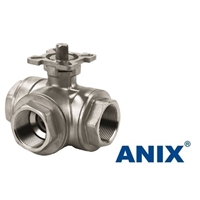
Picture of ANIX Stainless Steel 3-Way Ball Valve 1000 WOG  Threaded NPT

Got a business that’s going to be transporting liquid from point A to point B? Maybe it is solids or gasses that you plan on transporting. Whatever the situation is, it will be the ball valve that regulates the flow of these substances. Not only will they do just that, but they’ll also serve a variety of other essential functions. Therefore, it will be imperative to learn how to make sure you choose the right and highest quality brands for the task. The market is growing rapidly and there are several different types suited for different kinds of projects. It is easy to see why experts are expecting the market to grow to a $15 billion one by 2024.


What Exactly Is A Ball Valve?


Before learning how these valves work, it will be imperative to learn what they are, along with why you should consider using them in the first place. Whether you are dealing with industrial or residential valves, you are basically dealing with the same product. One is just designed to handle a larger load. This being said, an industrial ball valve is a piece of machinery that controls the flow of liquids, solids, and/or gases. These devices can start, stop, or redirect the flow of these substances.


Most experts would associate the ball valve with a plug valve, but there is a distinguishable difference between the two in the operation. The ball valve operates by utilizing a ball-shaped seating element, hence the name. Some individuals refer to these pieces as quarter-turn valves also because they normally only require a 25-degree turn to switch off and on. This gives them the benefit of operating much easier than other types of valves.


Breaking Down The Types


There are several types of ball valves commonly utilized in the industrial field. Knowing the difference between the valves and how they work could help you choose the best one for your project.


3-Way Ball Vale – Take the 3-way valve for instance. It’s commonly used and is named such because it offers 3 entry or exit points for gas or fluids to move through. Depending on the design and manufacturer, this design of valve can offer one inlet and two outlets or one outlet and two inlet ports. Choosing the one you need, depends on the type of project, and work you are looking to accomplish.


Top-Entry Ball Valves – Top-entry valves offer one distinct advantage over others, as they offer easier repair and maintenance. One just simply needs to remove the bonnet cover and they’ll be provided access to all the components. This variety shares several similarities with the globe variety many are familiar with. The only difference is the trim portion uses a ball device and consists of a single entity. These styles are typically constructed of cast metal.


Conclusion


This is just a touch on valves. One could write all day about these devices. The most important thing to note is they can be used for a wide range of applications in various projects.